The Throttle Position Sensor (TPS) is a vital component in modern internal combustion engines, particularly in vehicles with electronic fuel injection systems. Its primary function is to monitor the position of the throttle valve or throttle plate in the engine's air intake system and provide this information to the Engine Control Unit (ECU) or Powertrain Control Module (PCM).
Here are some key points about the Throttle Position Sensor:
1. Function:
- The TPS continuously detects and reports the angle or position of the throttle valve to the ECU/PCM. This data helps the engine management system determine the appropriate air-fuel mixture for efficient combustion and optimal engine performance.
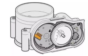
2. Location:
- The TPS is usually mounted on the throttle body assembly, connected to the throttle plate or shaft. In some designs, the TPS is integrated into the throttle body assembly itself.
3. Types of TPS:
- TPS can be either a potentiometer or a Hall-effect sensor. Potentiometric TPS units change resistance as the throttle is opened or closed, while Hall-effect sensors generate a voltage signal based on the magnetic field from the throttle's position.
4. Output Signal:
- The TPS typically sends a voltage signal to the ECU that varies depending on the throttle position. This signal helps the ECU adjust fuel delivery, ignition timing, and other parameters for optimal engine performance.
5. Idle Control:
- The TPS is critical for controlling the engine's idle speed. By monitoring the throttle position, the ECU can adjust the idle air control valve to maintain a stable idle speed when the throttle is closed.
6. Diagnosis and Troubleshooting:
- A malfunctioning TPS can lead to drivability issues such as poor acceleration, stalling, rough idling, and incorrect transmission shifting. Diagnostic trouble codes (DTCs) related to the TPS can trigger the Check Engine Light.
7. Maintenance:
- Regular maintenance and inspection of the TPS are essential to ensure proper engine performance. Cleaning the throttle body and checking TPS functionality during routine service can help prevent drivability issues.
In summary, the Throttle Position Sensor plays a crucial role in maintaining efficient engine operation by providing real-time throttle position information to the engine control system. Monitoring and ensuring the proper functioning of the TPS are essential for optimal engine performance, fuel efficiency, and overall driving experience.

Working Principle of Throttle Position Sensor
The Throttle Position Sensor (TPS) is a key component in modern engine management systems, providing crucial information about the position of the throttle valve to the Engine Control Unit (ECU) or Powertrain Control Module (PCM). Here's a breakdown of the working principle of the Throttle Position Sensor:
1. Sensor Type:
The Throttle Position Sensor can be of a potentiometric type or a Hall-effect sensor. These sensors work using different principles to detect the throttle position accurately.
-
Potentiometric TPS: Utilizes a variable resistor (potentiometer) that changes its resistance based on the throttle position. As the throttle valve moves, the wiper of the potentiometer changes the output voltage, which the ECU interprets to determine throttle position.
-
Hall-effect TPS: Employs a Hall-effect sensor that generates a voltage signal in response to changes in the magnetic field caused by the motion of the throttle valve. The ECU processes this voltage signal to determine the throttle position.
2. Throttle Position Detection:
- When the driver presses the accelerator pedal, it activates the throttle linkage mechanism, which opens or closes the throttle valve in the intake manifold.
- The TPS is mounted on the throttle body and typically consists of a sensor and a throttle shaft that rotates as the throttle valve moves.
- The sensor detects the rotational motion of the throttle shaft and transmits this information to the ECU in real-time.
3. Signal Output:
- As the throttle valve position changes, the TPS sensor generates a variable voltage signal proportional to the throttle position angle.
- This voltage signal is sent to the ECU, which interprets the data and uses it to adjust fuel delivery, ignition timing, and other engine parameters to optimize performance.
4. Operating Range:
- The TPS operates within a specific voltage range (often around 0.5 to 4.5 volts) corresponding to the full range of throttle movement from closed to wide open throttle positions.
- The ECU uses this voltage range to determine the throttle opening and adjust engine operation accordingly.
5. Feedback Loop:
- The ECU continuously monitors the TPS signal to ensure that the throttle position matches the driver's input. Any discrepancies or irregularities can trigger diagnostic trouble codes (DTCs) and potentially lead to drivability issues.
6. Importance:
- The accurate functioning of the TPS is crucial for precise fuel injection, efficient engine performance, emission control, and overall drivability of the vehicle.
In summary, the Throttle Position Sensor plays a critical role by providing real-time feedback on the throttle position to the engine control system, enabling precise control of fuel delivery and engine operation based on driver input and driving conditions.

Types of Throttle Position Sensor
Throttle Position Sensors (TPS) are vital components in modern engine control systems, providing crucial information about the throttle position to the Engine Control Unit (ECU). There are primarily two types of Throttle Position Sensors commonly used in vehicles: potentiometric sensors and Hall-effect sensors. Here is an overview of these two types:
1. Potentiometric Throttle Position Sensors:
Potentiometric TPS, also known as resistive TPS, operate based on changes in resistance as the throttle opens or closes. This type of sensor uses a variable resistor (potentiometer) to detect the throttle position.
Working Principle:
- The potentiometric TPS consists of a resistive track and a movable contact or wiper.
- As the throttle valve moves, the wiper changes its position on the resistive track, altering the electrical resistance.
- The movement of the wiper results in a change in voltage output, which is then sent to the ECU for throttle position calculation.
Advantages:
- Simple design.
- Cost-effective compared to Hall-effect sensors.
Disadvantages:
- Can be prone to wear and mechanical failure due to the moving parts.
- Less durable compared to Hall-effect sensors.
2. Hall-effect Throttle Position Sensors:
Hall-effect TPS work based on the Hall effect, where a voltage is generated when a conductor (the Hall sensor) moves through a magnetic field (created by the throttle position).
Working Principle:
- A Hall-effect TPS consists of a Hall-effect sensor that produces a voltage signal in response to changes in the magnetic field caused by throttle movement.
- As the throttle valve opens or closes, the magnetic field changes, generating a voltage output that corresponds to the throttle position.
- The ECU interprets this voltage signal to determine the throttle position accurately.
Advantages:
- No physical contact or moving parts, enhancing reliability and longevity.
- Better accuracy and repeatability compared to potentiometric sensors.
- Less susceptible to wear and tear.
Disadvantages:
- Generally more expensive than potentiometric sensors.
- Sensitive to electromagnetic interference.
Both potentiometric and Hall-effect TPS have their advantages and limitations, and the choice between the two depends on factors such as application, cost considerations, accuracy requirements, and environmental factors. Manufacturers select the type of TPS based on the specific needs of the vehicle's engine system and the desired performance characteristics.

Hall Throttle Position Sensor
Here is some additional information regarding a Hall Throttle Position Sensor, incorporating Hall-effect technology:
Hall Throttle Position Sensor (Hall TPS):
-
Working Principle: A Hall TPS employs a Hall-effect sensor to detect changes in the magnetic field generated by the movement of the throttle valve. This movement results in a voltage signal generated by the Hall-effect sensor.
-
Accuracy and Precision: Hall-effect sensors are known for their accuracy and precision in detecting changes in magnetic fields, making them ideal for applications where precise throttle position sensing is essential.
-
Contactless and Durable: Hall TPS sensors are contactless, which means they do not have physical contact or moving parts that are prone to wear. This characteristic enhances their durability and reliability over time.
-
Signal Output: When the throttle valve moves, the Hall TPS generates a voltage signal directly proportional to the throttle position. The Engine Control Unit (ECU) uses this signal to adjust fuel delivery, ignition timing, and other engine parameters for optimal performance.
-
Advantages:
- Enhanced reliability due to the absence of moving parts.
- Improved accuracy and repeatability.
- Higher resistance to wear and tear compared to potentiometric sensors.
-
Disadvantages:
- Generally more expensive than potentiometric sensors.
- Susceptible to electromagnetic interference.
Throttle Position Sensors using Hall-effect technology are commonly found in modern vehicles due to their reliability and accuracy in providing precise throttle position feedback to the engine control system. These sensors play a crucial role in optimizing engine performance, fuel efficiency, and overall drivability.
Slide Resistance Throttle Position Sensor
Slide resistance throttle position sensor, also known as linear output throttle position sensor, variable resistive throttle position sensor, potential ribbon throttle position sensor. At present, the dual variable resistance throttle position sensor is being applied to a large number of vehicles.
The sliding resistance throttle position sensor is a three-wire sensor, wherein the two pins are at both ends of the resistor and serve as the power terminal and the iron terminals by the engine ECU, and the third pin is connected to the sliding contact. The throttle shaft is linked to the contact (or contact). When the throttle is rotated, the sliding contact can move on the resistor, causing a change in the sliding contact potential to convert the throttle position signal to a voltage value. Since this voltage is linear, it is also known as a linear output throttle position sensor. According to this linear voltage value, the ECU can sense the opening degree of the throttle to correct the ECU.
The throttle position sensor is tested as follows:
Testing a Throttle Position Sensor (TPS) is a crucial step in diagnosing potential issues in the vehicle's engine performance. Here's a general guide on how to test a TPS:
Tools Required:
- Multimeter
- Back-probe or paper clips for accessing TPS wiring terminals
- Vehicle service manual for specifications and testing procedures
Testing Procedure:
-
Visual Inspection:
- Ensure the TPS wiring and connector are in good condition.
- Check for any signs of wear, corrosion, or damage on the sensor and its wiring.
-
TPS Resistance Test:
- Set the multimeter to the resistance (ohms) function.
- Disconnect the TPS connector.
- Attach the multimeter leads to the TPS terminals based on the specifications provided in the service manual.
- Gradually move the throttle from closed to open position while observing the resistance readings on the multimeter.
- Compare the resistance values to the manufacturer's specifications. A smooth and consistent change in resistance as the throttle opens and closes indicates a functioning TPS.
-
TPS Voltage Test:
- Set the multimeter to the voltage (DC) function.
- Connect the multimeter leads to the TPS wiring harness terminals with the key in the ON position but the engine off.
- Gradually open and close the throttle while observing the voltage readings on the multimeter.
- The voltage should increase or decrease smoothly and consistently as the throttle position changes. Compare the values to the manufacturer's specifications.
-
Output Signal Test:
- Use a scan tool or oscilloscope to monitor the TPS output signal waveform.
- Open and close the throttle while observing the signal pattern.
- The signal should show a smooth and consistent transition without any sudden drops or spikes.
-
Reinstallation and Retesting:
- After testing, reconnect the TPS connector and ensure it's properly secured.
- Clear any trouble codes that may have been stored in the ECU before retesting the vehicle.
If the TPS fails any of the tests or shows inconsistent readings, it may indicate a faulty sensor that requires replacement. Always refer to the specific testing procedures outlined in the vehicle service manual for accurate testing protocols and specifications tailored to your vehicle's make and model.